What Is Reference Plane In Engineering Drawing

What Is Reference Plane Horizontal And Vertical Plane Youtube Engineering drawing graphics is the creation and representations of physical objects locations on plain paper or in electronic format in the form of (2d) 2. The purpose of this guide is to give you the basics of engineering sketching and drawing. we will treat “sketching” and “drawing” as one. “sketching” generally means freehand drawing. “drawing” usually means using drawing instruments, from compasses to computers to bring precision to the drawings. this is just an introduction.

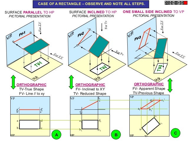
Projection Of Plane Engineering Drawing After studying this chapter, you will be able to. draw the projections of the plane surfaces of regular shapes like triangles, squares, rectangles, circles or semicircles in the following positions: parallel to one of the reference planes. perpendicular to one and inclined to the other reference plane. inclined at angles other than 0° or 90. Projections and views. a three dimensional object can be represented in a single plane, such as on a sheet of paper, using projecting lines and planes. all projection theory is based on two variables: line of sigh t (projecting lines) and plane of projection. a line of sight (los) is an imaginary line between an observer’s eye and an object. Draw the horizontal locus lines through b 2, and. b. 6. with center a and radius ab1, draw an arc to cut the locus line drawn through b2 at b. connect ab, the top view of the line ab. 7. with center a' and radius a'b. 2 , draw an arc to cut the locus line drawn through connect a'b', the front view of the line. Principal planes: the planes on which the projections are obtained are called the principal planes. examples of principal planes are horizontal and vertical planes. secondary planes: secondary planes are of two types: (i) perpendicular planes (ii) oblique planes (i) perpendicular planes: these planes can be divided into the following sub types: 1.

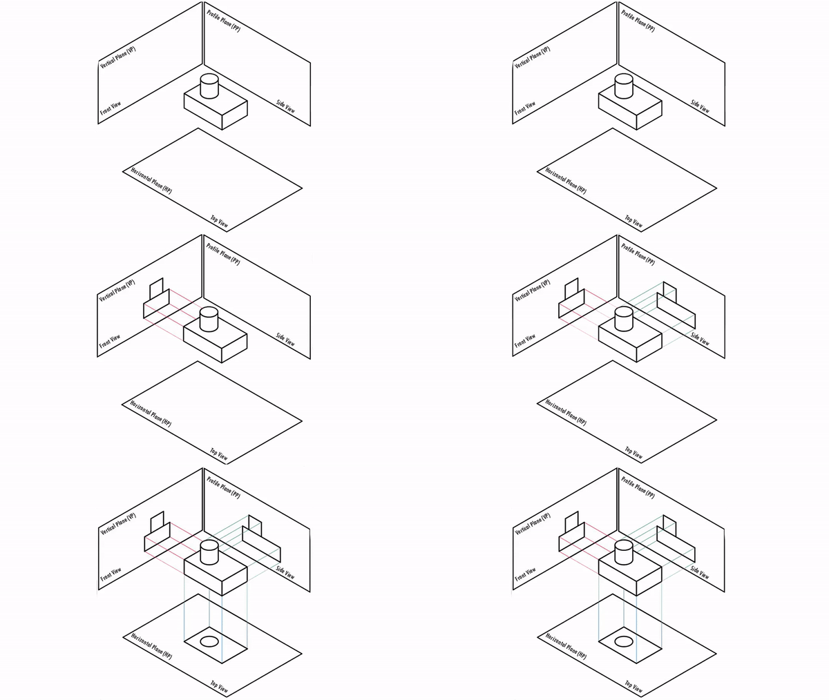
Engineering Drawing Sevenmentor Draw the horizontal locus lines through b 2, and. b. 6. with center a and radius ab1, draw an arc to cut the locus line drawn through b2 at b. connect ab, the top view of the line ab. 7. with center a' and radius a'b. 2 , draw an arc to cut the locus line drawn through connect a'b', the front view of the line. Principal planes: the planes on which the projections are obtained are called the principal planes. examples of principal planes are horizontal and vertical planes. secondary planes: secondary planes are of two types: (i) perpendicular planes (ii) oblique planes (i) perpendicular planes: these planes can be divided into the following sub types: 1. Example: application of precedence. profile or side views are represented by small letters with double dashes eg. a. the line of intersection of vp and pp is denoted as x1y 1. projectors and the lines of the intersection of planes of projections are shown as thin lines. draw x1y1 line to represent the line of intersection of vp and pp. Engineering drawing is a systematic process of communicating design ideas through documentation. it involves conceiving ideas and representing objects through systematic lines on paper. orthographic projection is a method of projection where projectors from points on an object are parallel and perpendicular to projection planes.

Comments are closed.