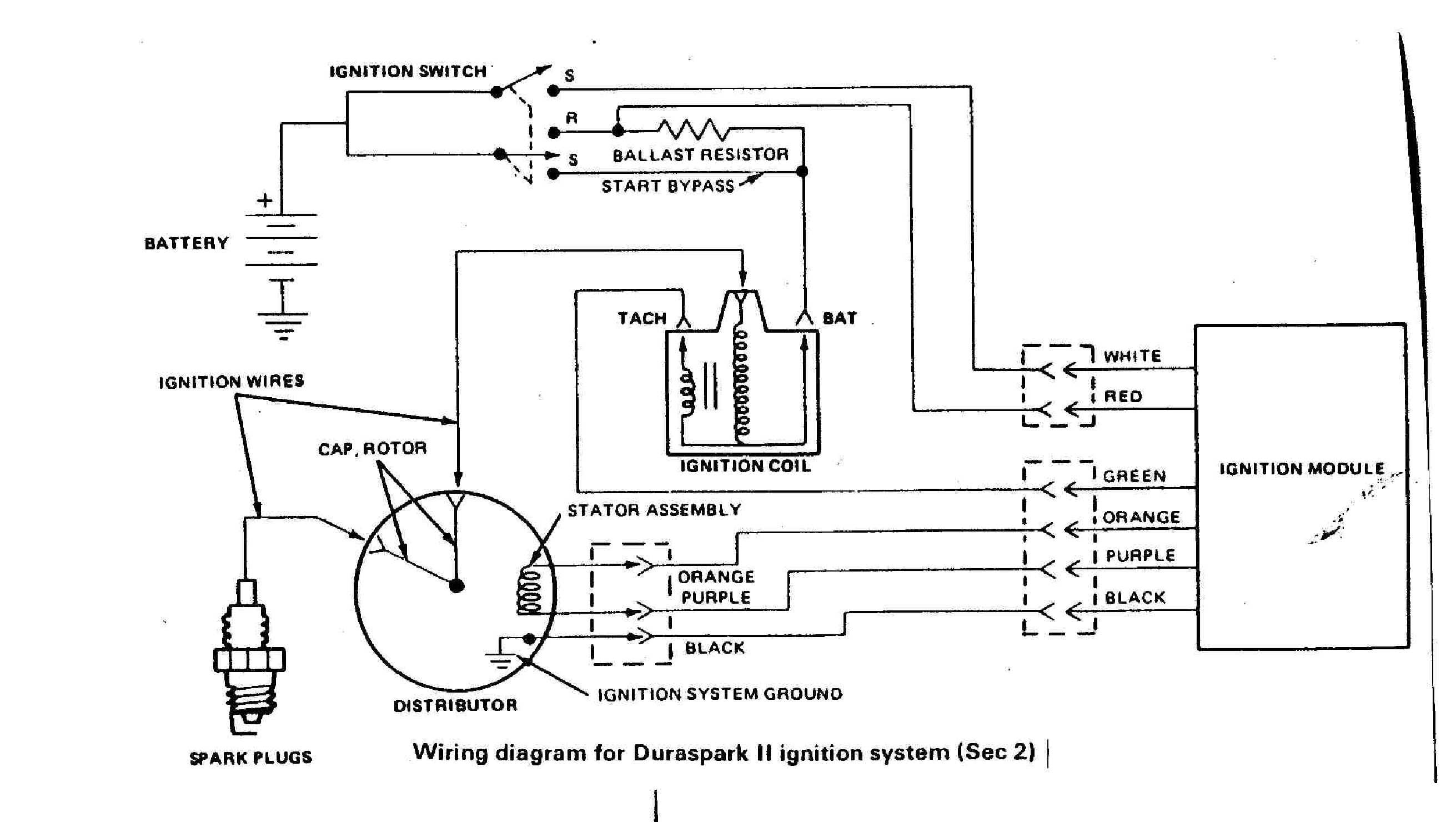
Wiring Diagram For Johnson Outboard Ignition Switch в Wiring Digital

Wiring Diagram For Johnson Outboard Ignition Switch Wiring23 The wiring diagram for the johnson outboard ignition switch typically includes the following connections: battery positive ( ) terminal: connects to the ignition switch terminal labeled “b ” or “bat.”. ignition switch terminal: connects to the ignition coil and other electrical components. Capt. chris of buzzards bay takes a look at a common evinrude johnson ignition switch with integrated clip on safety lanyard (brp part no. 5005801). you'll s.

Johnson Ignition Switch Wiring Diagram Q A For Boat Owners I need help wiring an ignition key switch for a 76 johnson outboard motor (think its 76??). motor is hooked up to steering wheel and throttle so there are 2 black wires from the throttle. the rest are from the motor itself. the switch is a 6 terminal push to choke. ill post pics so you guys can get a better understanding. one blue wire has with. Layout of the wiring diagram. the wiring diagram for a johnson outboard ignition switch includes four wires: red, yellow, green, and black. the red wire is for power, the yellow wire is for ground, the green wire is for start, and the black wire is for ignition. these wires should be clearly labeled on the wiring diagram to avoid confusion. Re: 1966 33hp johnson, electric start, no generator, wiring diagram needed pic #1 that is the cut out switch. should have two wires to the center post: one black coming from under the flywheel mag plate and the other going on to an "m" terminal of the ignition switch. Tighten the nut. advance to the 8 o'clock position on the ignition switch's rear panel, where you will find the "a" terminal. loosen the nut and slip the spade connector of the solid purple wire beneath it. tighten the nut. go clockwise again, to the second "m" terminal. loosen the nut, as you have with the other terminals, and slide the spade.

Wiring Diagram For Johnson Outboard Ignition Switch Database Wiring Re: 1966 33hp johnson, electric start, no generator, wiring diagram needed pic #1 that is the cut out switch. should have two wires to the center post: one black coming from under the flywheel mag plate and the other going on to an "m" terminal of the ignition switch. Tighten the nut. advance to the 8 o'clock position on the ignition switch's rear panel, where you will find the "a" terminal. loosen the nut and slip the spade connector of the solid purple wire beneath it. tighten the nut. go clockwise again, to the second "m" terminal. loosen the nut, as you have with the other terminals, and slide the spade. Tighten key switch nut to 20 to 30 in. lbs. (27.1 to 40.7 n·m). caution assembly and installation of ignition switch must provide water drainage. to allow for the draining of moisture that comes through the lock cylinder, make sure the ignition switch is installed in a horizontal posi tion with the alignment flat up and the drain hole down. Symbols such as squares, circles, triangles, and lines are used to indicate switches, fuses, resistors, batteries, and more. understanding these symbols will make it easier to interpret the diagrams. 2. identify the power source. the first step in reading a wiring diagram is to locate the power source.

Johnson Outboard Ignition Switch Wiring Diagram Wiring Diagram Tighten key switch nut to 20 to 30 in. lbs. (27.1 to 40.7 n·m). caution assembly and installation of ignition switch must provide water drainage. to allow for the draining of moisture that comes through the lock cylinder, make sure the ignition switch is installed in a horizontal posi tion with the alignment flat up and the drain hole down. Symbols such as squares, circles, triangles, and lines are used to indicate switches, fuses, resistors, batteries, and more. understanding these symbols will make it easier to interpret the diagrams. 2. identify the power source. the first step in reading a wiring diagram is to locate the power source.

Johnson Ignition Switch Wiring Diagram

Johnson Outboard Ignition Wiring Diagram

Comments are closed.