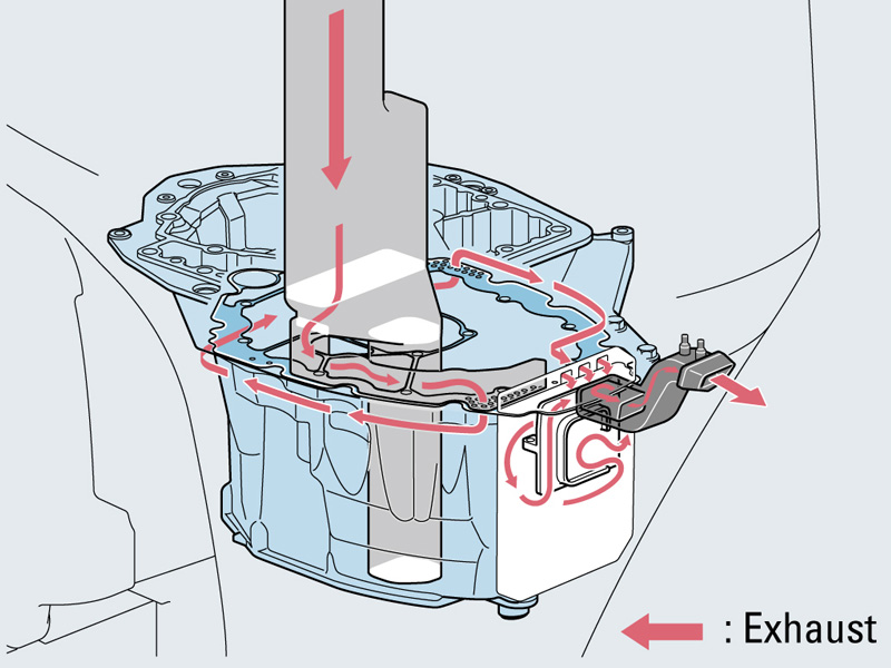
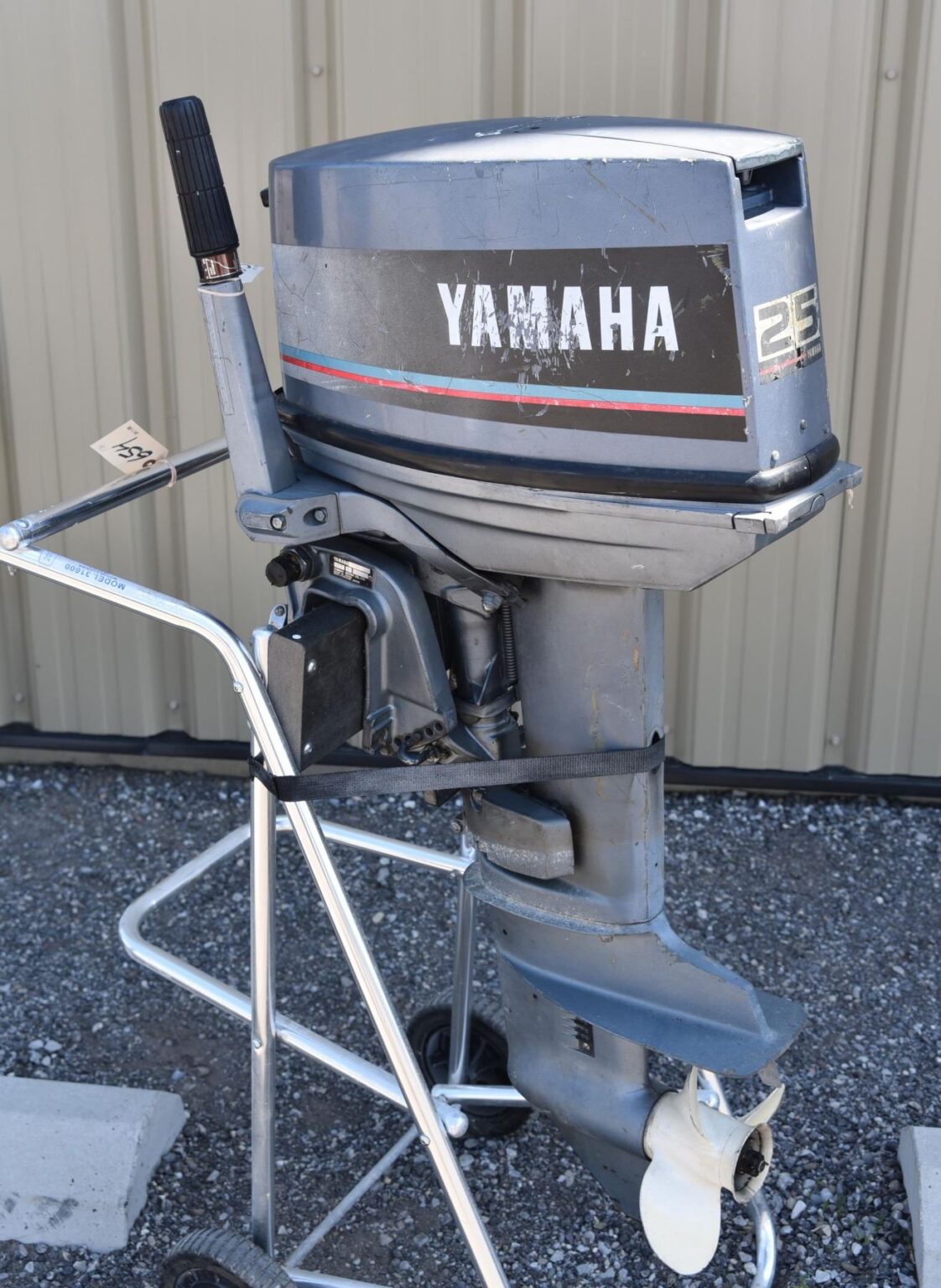
Yamaha 2 Stroke Outboard Cooling Diagram

Yamaha 2 Stroke Outboard Cooling Diagram Headcontrolsystem The cooling system of a yamaha outboard motor is designed to regulate the temperature of the engine and prevent overheating. it consists of several key components, including the water pump, thermostat, cooling passages, and the exhaust system. water pump: the water pump is responsible for circulating coolant through the engine. Mar 11, 2013. messages. 499. dec 22, 2021. #1. trying to educate myself tonight to solve overheating issues on several motors. i'm looking for the path cooling water takes through a yamaha "2 stroke" , such as . pickup water pump thermostat exhaust cylinders exhaust prop. not sure if i have that in the right order.

Cooling System News Cooling System Yamaha Outboard The cooling system on an outboard is a very simple and compact application. water is inducted through the lower unit by a water pump impeller, and then forced upward to circulate throughout the powerhead, and eventually exits through the exhaust system. there are a couple of things pertaining to the outboard cooling system that need regular. Read this manual carefully before operating this outboard motor. owner’s manual f150 lf150 lit 18626 12 45 63p 28199 3m e0 u63p3me0.book page 1 friday, december 7, 2018 1:45 pm. Elec electrical system checking the engine temperature engine temperature sensor resistance sensor (reference data): 1. remove the flywheel magnet cover. black yellow (b y)–black yellow (b y) 54.2–69.0 kΩ at 20 °c (68 °f) 2. disconnect the engine temperature sen 3.12–3.48 kΩ at 100 °c (212 °f) sor coupler a. Install the holders c and retaining plate note: apply engine oil to the flywheel magnet nut before installation. flywheel holder: 90890 06522 flywheel magnet nut: 240 n·m (24 kgf·m, 174 ft·lb) 11. reinstall the all removed parts. 8. install the stator coil bracket and stator coil.

Yamaha 2 Stroke Outboard Cooling Diagram Headcontrolsystem Elec electrical system checking the engine temperature engine temperature sensor resistance sensor (reference data): 1. remove the flywheel magnet cover. black yellow (b y)–black yellow (b y) 54.2–69.0 kΩ at 20 °c (68 °f) 2. disconnect the engine temperature sen 3.12–3.48 kΩ at 100 °c (212 °f) sor coupler a. Install the holders c and retaining plate note: apply engine oil to the flywheel magnet nut before installation. flywheel holder: 90890 06522 flywheel magnet nut: 240 n·m (24 kgf·m, 174 ft·lb) 11. reinstall the all removed parts. 8. install the stator coil bracket and stator coil. The main components of a 2 stroke yamaha outboard motor include the powerhead, exhaust system, fuel system, cooling system, and ignition system. the powerhead is the core of the motor and houses the cylinder, piston, and crankshaft. these components work together to convert the burning of fuel into mechanical power, which drives the propeller. Summary of contents for yamaha 8. page 1 owner’s manual u.s.a.edition lit 18626 08 33 6m8 f8199 1e page 2 emu25062 zmu01690 read this manual carefully before operating this outboard motor. keep this manual onboard in a waterproof bag when boating. this manual should stay with the outboard motor if it is sold.

Comments are closed.