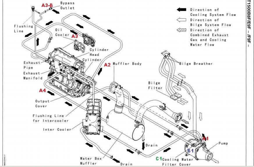
Yamaha Waverunner Cooling System Diagram

Yamaha Waverunner Cooling System Diagram Headcontrolsystem To check the cooling system hoses, trace these one at a time looking for cracks and fraying. if you spot any damage, they’ll need to be replaced. connect a garden hose to the cooling line. turn the hose on and then your waverunner. while it idles, inspect the back of the pwc to see if water is being ejected. In a yamaha waverunner, the cooling system consists of several essential components, including the water pump, thermostat, and heat exchanger. the water pump is responsible for circulating coolant throughout the engine, while the thermostat helps regulate the temperature by controlling the flow of coolant.

Yamaha Waverunner Cooling System Diagram Headcontrolsystem Page 114 powr engine unit 5. measure: • compression pressure out of specification → refer to steps (b) and (c). minimum compression pressure (reference data): 1,150 kpa (11.5 kgf cm , 164 psi) measurement steps: a. with the throttle wide open, crank the engine until the reading on the compres sion gauge stabilizes. Page 70 yamaha motor corporation, usa printed in usa × 1 cr jan. 2002 – 90894 64630 60 (fx1000 a) printed on recycled paper view and download yamaha waverunner fx140 service manual online. waverunner fx140 boat pdf manual download. Summary of contents for yamaha waverunner xlt1200. page 1 waverunner xlt1200 service manual manuel d’entretien wartungshandbuch manual de servicio 460068 f0v 28197 2d c1 page 2 notice this manual has been prepared by yamaha primarily for use by yamaha dealers and their trained mechanics when performing maintenance procedures and repairs to. Cooling water enters the ski through 1 hose, but exits at at least 4 different locations. once you have traced the entry point and the 4 exits and understand where the water came from for each point, you will have a pretty good understanding of how the system works. 2008 yamaha fx ho cruiser. 2010 hurricane sundeck 2100.
40 Yamaha Waverunner Cooling System Diagram Wiring Diagrams Manual Summary of contents for yamaha waverunner xlt1200. page 1 waverunner xlt1200 service manual manuel d’entretien wartungshandbuch manual de servicio 460068 f0v 28197 2d c1 page 2 notice this manual has been prepared by yamaha primarily for use by yamaha dealers and their trained mechanics when performing maintenance procedures and repairs to. Cooling water enters the ski through 1 hose, but exits at at least 4 different locations. once you have traced the entry point and the 4 exits and understand where the water came from for each point, you will have a pretty good understanding of how the system works. 2008 yamaha fx ho cruiser. 2010 hurricane sundeck 2100. Title: gp760 1200 service manual author: ymc, ltd. created date: 20010828203008z. Buy now. secure transaction. $30.99. description reviews q&a. this comprehensive service repair manual is designed for the yamaha waverunner xl760, xl1200, and xl700 models, spanning from 1999 to 2004. it encompasses a wide array of service and repair procedures, including assembly, disassembly, wiring diagrams, and more.

Comments are closed.